Windows Devices
How to Image a Windows Device
Connect device to power and Internet and power on
Press F12 repeatedly until the system settings
Select the USB flash drive
Once competed all steps- remove flash drive Type EXIT and press enter key
Leave device on until completely finished will be at login screen.
*If device is not in intune or doesn't go to login screen (just sits at the Country screen) then send Ricky a message. Be prepared to possibly have to bring in.
Updating Firmware on Dell
(Instructions are for Latitude 3310)
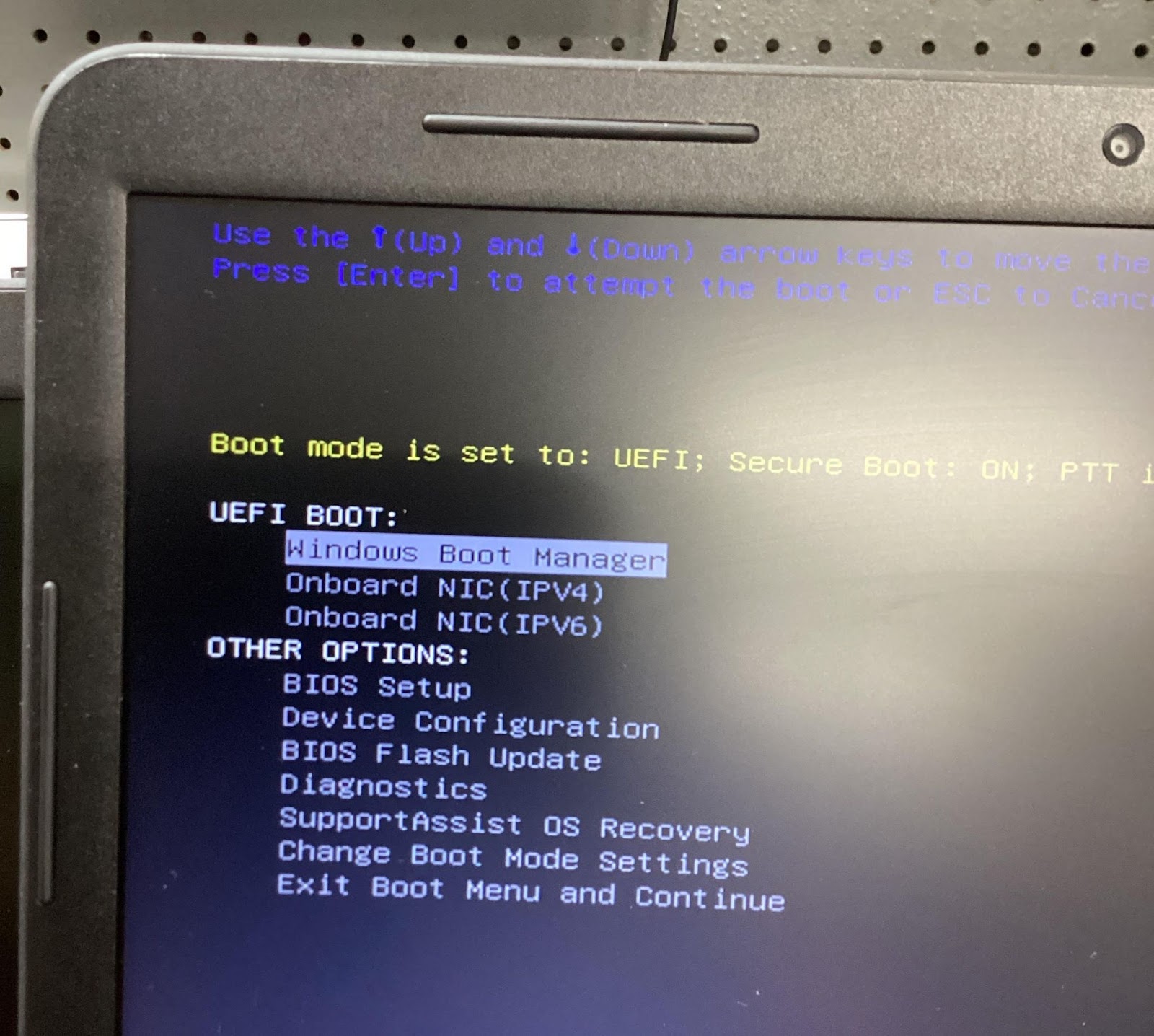
- Plug in Power Cable, flash drive, and turn on laptop and press F12 repeatedly.
- Use Down Arrow-Under Other Options find BIOS Flash Update - Press Enter
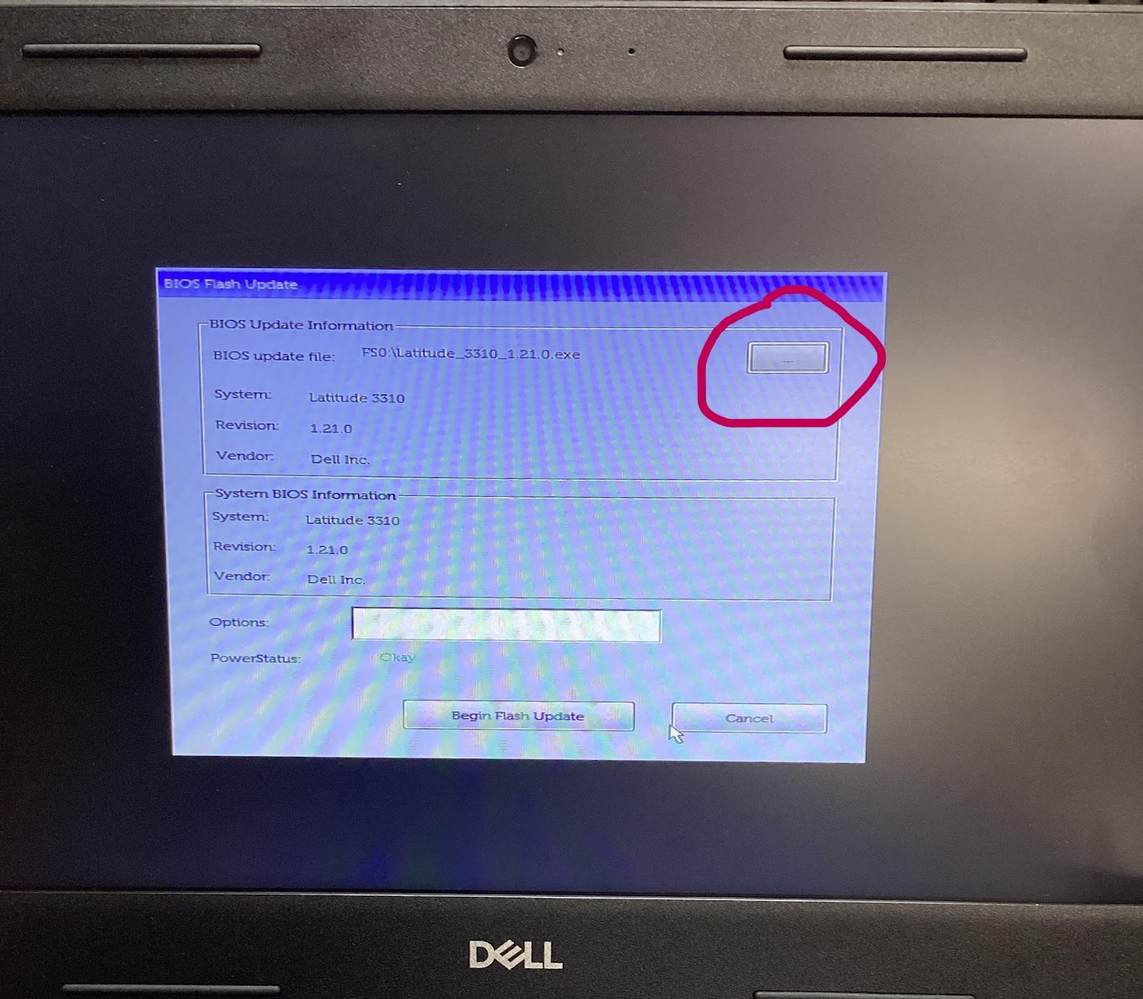
- Click Gray Box at top of screen reen (has 3 dashes or dots)
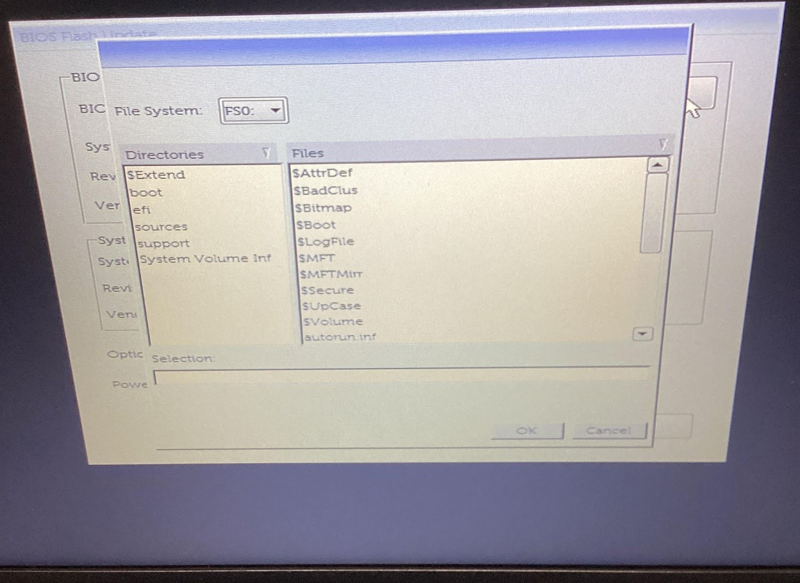
- First Option is FS0
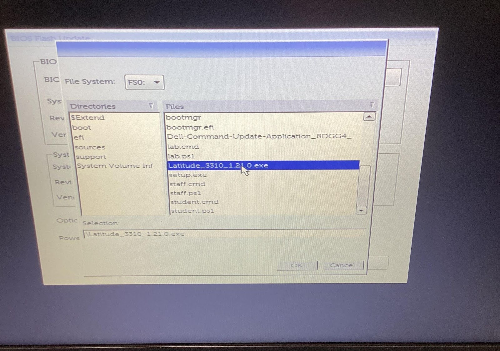
- Go to the bottom of the list. Select Latitude_3310_xxxxx.exe and click OK. If doing an different model make sure you have the correct firmware for that model. If you don’t see the exe on FS0 go through FS1, FS2, etc to find it.
- There will be a message to please wait.
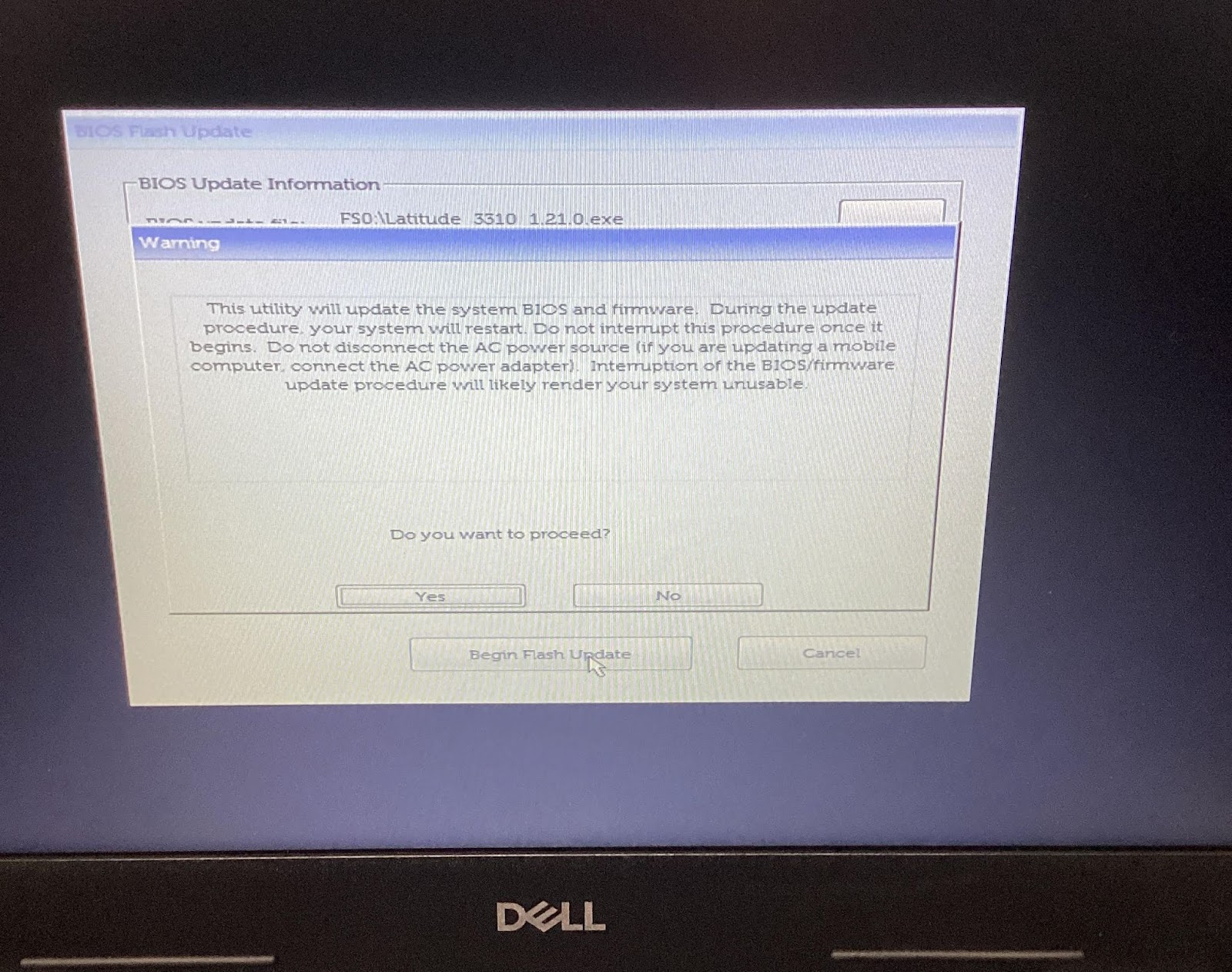
- There will be a message to ask if you are sure. Press Yes
- Laptop will restart
- This is the screen you will be looking for to see the progress.
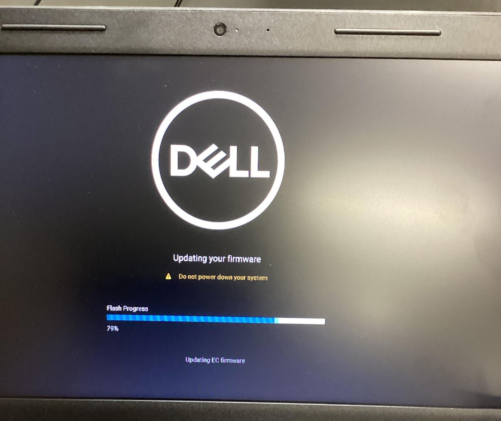
- When finished the laptop will restart and it is done.
Dell Diagnostic LED Blink Codes
Diagnostic LEDs
Instead of beep codes, errors are indicated via the bicolor Battery Charge/Status LED. A specific blink pattern is followed by flashing a pattern of flashes in amber, followed by white. The pattern then repeats.
The diagnostic pattern will consist of a two-digit number being represented by a first group of LED blinks (1 through 9) in amber, followed by a 1.5 second pause with the LED off, and then a second group of LED blinks (1 through 9) in white. This is then followed by a three second pause, with the LED off, before repeating over again. Each LED blink takes 1.5 seconds.
The system will not shutdown when displaying the Diagnostic Error Codes.
Diagnostic Error Codes will always supersede any other use of the LED. For instance, on laptops, battery codes for Low Battery or Battery Failure situations will not be displayed when Diagnostic Error Codes are being displayed.
| BLINKING PATTERN | PROBLEM DESCRIPTION | SUGGESTED RESOLUTION | |
|---|---|---|---|
| AMBER | WHITE | ||
| 2 | 1 | CPU failure | Replace the system board. |
| 2 | 2 | System board failure (included BIOS corruption or ROM error) | Flash latest BIOS version. If problem persists, replace the system board. |
| 2 | 3 | No memory/RAM detected | Confirm that the memory module is installed properly. If problem persists, replace the memory module. |
| 2 | 4 | Memory/RAM failure | Replace the memory module. |
| 2 | 5 | Invalid memory installed | Replace the memory module. |
| 2 | 6 | System board/Chipset error | Replace the system board. |
| 2 | 7 | LCD failure | Replace the LCD module. |
| 2 | 8 | LCD Power rail failure | Replace the system board. |
| 3 | 1 | CMOS battery failure | Replace the RTS battery. |
| 3 | 2 | PCI or Video card/chip failure | Replace the system board. |
| 3 | 3 | BIOS Recovery Image not found | Flash latest BIOS version. If problem persists, replace the system board. |
| 3 | 4 | BIOS Recovery Image found but invalid | Flash latest BIOS version. If problem persists, replace the system board. |
For diagnostics pattern 2-amber, 8-white connect an external monitor to isolate between system board or graphics controller failure.